Creating a Castle in Blender Part 2
Good day everyone!
Welcome to Part 2 to of creating a castle in a desert. In this tutorial I’ll show you how to finish off your scene by texturing, rendering, and compositing it.
Because the computer I am using is in a place where it is best to be quiet, I had to make Part 2 a text tutorial. Hope it works for you.
Here we go!
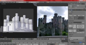
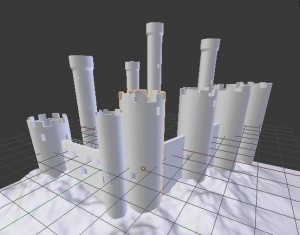
This is where we left off.
For starters, just select the selected castle tower.
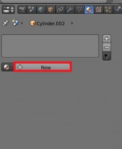
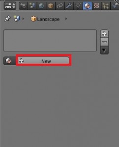
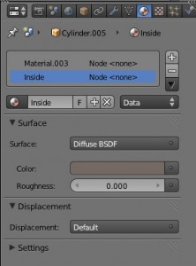
Go to the materials tab and add a new material.
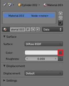
Leave everything as is; just press the selected button.
Select the Image Texture.
Press the “Open” button.
I used a texture called BrickOldDirty0132_4_L. Just grab it and select “Open Image.”
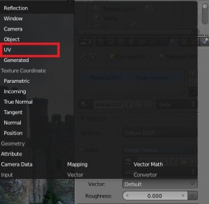
Set the Vector as “UV.”
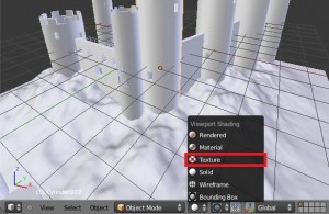
Set the Viewport Shading to “Texture” (so we can see what we are doing). Also hide the landscape by pressing H so the texturing process goes a little faster.
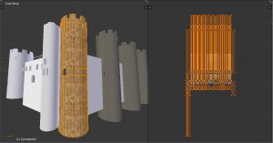
You will notice that the four towers (you should have linked them together in the first tutorial; if not, just select them all and press Ctrl+L and link the Object Data) will be a brownish-gray color. This is because they need to be unwrapped. So go ahead and select the brick texture in the UV Image Editor.
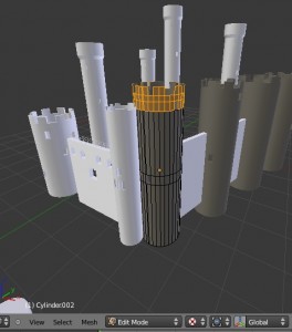
Select one of the towers and press Tab to get into Edit Mode.
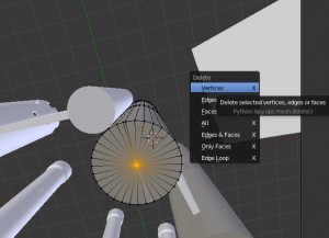
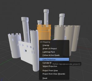
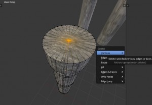
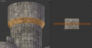
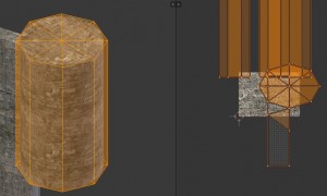
Normally I would add seams, etc., to this cylinder, but there’s a cheat method you can use to unwrap this cylinder without too much trouble. Before you unwrap this cylinder, be sure to delete the bottom middle vertex of the tower, as it will not be needed and gets in our way. One you do this, you can go ahead and select the entire tower, press U, and select “Cube Projection.”
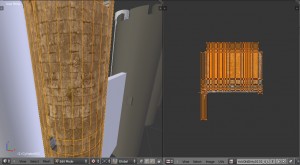
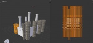
It should look pretty similar to this:
With a little adjusting, stretching, and scaling to the unwrapped mesh, you should be able to get a good looking result. You may see some glitches but you shouldn’t notice them in the render.
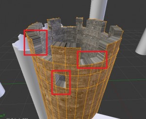
But wait, something is wrong!
Yes, this is caused by the solidify modifier. Because it has not been unwrapped, it looks very stretched. This will be taken care of in a little bit, just don’t freak out.
Once you press Tab and get out of Edit Mode, the other towers linked should also turn into textured towers.
So now you can quickly do the same with the other towers; go to the material tab, add the same stone material to them, and just unwrap them using the Cube Projection and it should work fine. (Be sure to delete the bottom middle vertex of each one though, otherwise a big circle will be in your way. And if you don’t add the material to the tower, you won’t see any texture on the tower when you unwrap it.)
As for the towers in the back, if you don’t delete the top vertex then the whole thing becomes messed up, so delete the top one as well and unwrap them with the Cube Projection as well (you can delete the bottom middle vertex though) and assign the stone material to them. You may have to do some tweaking to the unwrapping as well.
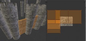
As for the walls, take the selected ones and, after adding the same material, go into Edit Mode, press U, and click Cube Projection.
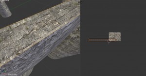
The top part of the wall will be stretched, so just scale it thinner on the Y axis in the UV Image Editor. (Don’t worry about anything else.)
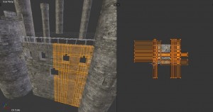
Now for the front gate; assign the stone material to it, and unwrap it using the cube projection.
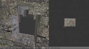
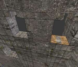
The problem here is that each of the “windows” will be all stretched in the inside, so you will manually have to go and adjust each one.
So you have to just manually adjust each window piece (it goes faster if you use the mirror modifier and if you select more than one face at once).
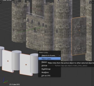
Take the two front walls and then select one of the already textured walls (not the front wall), press Ctrl+L, and select Object Data. The front walls should turn textured and also be taller.
Select one of the small front towers, add the same stone material to it, go into Edit Mode, press U, and Cube Projection it. It should already be pretty satisfactory. You can just leave it as is.
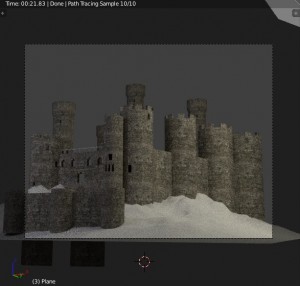
Feel free to give it a quick render now:
Not bad. Let’s get into the sand now.
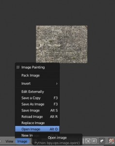
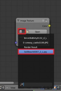
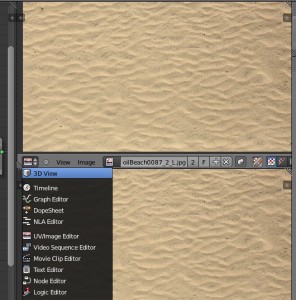
Go to your UV Image Editor and click the Image Button, and then press Open Image.
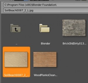
Open up this sand texture, SoilBeach0087_2_L. We will use this as a reference picture (and also as part of the sand texture).
Add a new material to the sand.
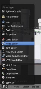
Change the left viewport into the Node Editor.
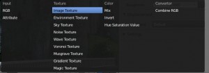
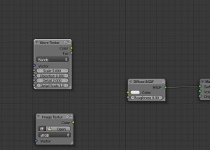
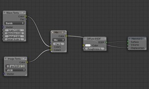
In the material nodes, press Shift+A to open the “Add” menu and create two textures: a Image Texture and a Wave Texture.
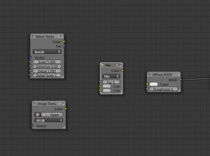
Press Shift+A again, go into “Color,” and add a Mix Node.
Choose the sand texture in the Image Texture node.
Connect the Image Texture node to the bottom input of the Mix node, and the Wave texture to the top input. Then connect the Mix node to the Displacement input of the Material Output.
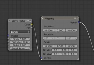
Go to “Vector” and choose the only option, “Mapping.” Attach this after the wave texture and connect it to the top node input of the mix node. Simply change the “Scale” of X, Y, and Z to 0.5, rather than 1. This will give a less extreme bump map to the sand.
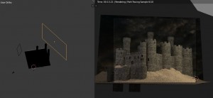
We are going to need to see what we are doing, so we need to open up a third window. Split the right window in two, and change one of the new windows to the 3d view.
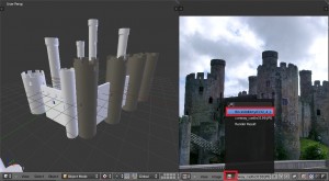
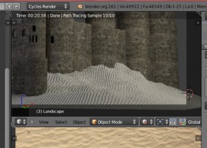
Change the Viewport Shading to Rendered and see how it looks.
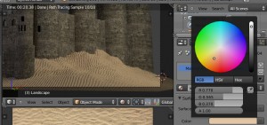
Not bad, but we need some color, obviously. So go to your Material’s color and use the eyedropper tool on the sand texture to get the right sand color. If the eyedropper tool does not work (sometimes it doesn’t) you can left-click on any part of the image, and on the bottom of the viewport it should show you the color statistics of the area you are clicking on. (You might have to do some remembering.)
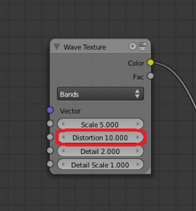
Change the Distortion of the Wave Texture to 10.
It’s looking good now. Let’s add the background.
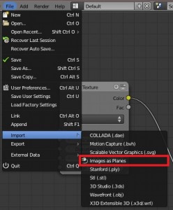
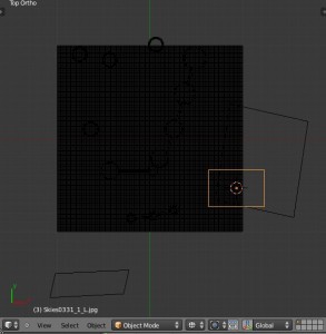
If you haven’t known about the “Images to Planes” plug-in, it’s very handy. If you have not enabled it yet, do so by going to the User Preferences and typing in “Images” in the search bar – it should come up. Check it, and go to the top menu and click “File.” If you go to “Import,” you should see the plug-in there.
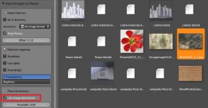
Select the sky texture, Skies0331_1_L (you can use whatever sky texture you want but this works pretty well), and make sure to check “Use image dimensions.”
You can change the Node Editor back to 3d View.
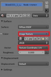
Cycles won’t like the sky’s material, so make sure to go to the materials tab and press the “Use Nodes” button. It will come out with the default Cycles Material, but simply just change the color to the Image Texture, set the image to the sky, and the Vector to UV.
Now just fiddle with the sky plane until it matches up with the camera view. (You can merge the rendering 3d viewport with the UV Image Editor viewport now – you don’t need the sand texture anymore.)
Do your best to try and get the castle to match up with the sky background, in terms of lighting.
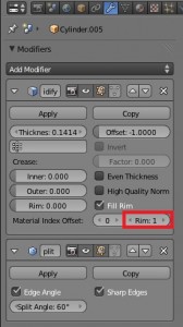
Do one important thing though, before rendering – make sure you assign a new material to the soldify modifier, otherwise it will all look stretched on that part. So just select one of the towers and press the “+” button and the new material button.
Change the color of the material to a darkish brown color. That should work if you don’t get too close to the castle. Then go to the Solidify modifier and next to “Material Index Offset” there should be a button that says “Rim: 0″ – change the Rim to 1. This will change the material of the Solidifier to the 2nd material.
Make sure to do this for all towers that have a solidify modifier.
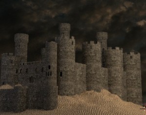
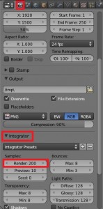
Once you have done this you can do your big render. For a final render, you can change the samples to 200.
Once you have a good resolution, make sure to change it to 100% and press F12.
My render (on a pretty fast laptop) took about 1 hour and 10 minutes, and the render is pretty clean.
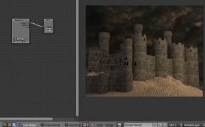
Once you are done with your render, head over to the Node Editor and hit the Compositing Nodes button. Be sure to press “Use Nodes.”
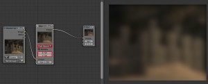
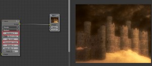
We are going to add a quick glow to the scene. Add a Blur node, stick it between the Compositor and the Render Layer, change the blur type to Fast Gaussian, and change the X and Y values to 50.
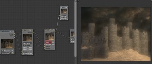
Add a Mix node after the Blur node, and put the output of the blur node into the top input of the Mix node, and the Render Layer output into the bottom input.
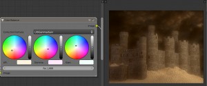
Now we are going to add some color balance. Add a Color Balance node and place it after the Mix node. Change the colors to: Lift: FFF4DF (for Hex); Gamma: FFE8FC; and Gain: F2FFFA.
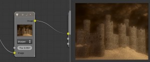
Also we are going to add a sharpen filter to bring out the stones more. Go to the Filters, choose “Filter,” change the type to Sharpen, and set the Fac value to 0.05.
Let’s add some quick glare to the scene. Add a glare node and put it in after the sharpen node. Change the Threshold to 0.1 and the Iterations to 2.
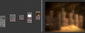
Now for the Vignette: Add the Lens Distortion node, change the Distort Value to 1, add a Math node, change the type to Greater Than, change the Fac value to 0, add a Blur node, change the type to Fast Gaussian and the X and Y values to 128, add a Mix node, change the type to Multiply and the Fac value to 0.9, and put the blur node’s output in the mix node’s bottom input and the glare node’s output into the top input of the mix node. (Whew.)
Hooray! You are finished now. If you have any questions feel free to post a comment.
